Réflexion sur … les connecteurs (MàJ Janv. 2024)
Cette mise à jour reprend les grandes lignes de la précédente version, en apportant un complément et une actualisation de l’état actuel de la connaissance sur les connecteurs, concernant leur conception, les sollicitations, les axes de travail, les différents montages, etc …
La Réflexion Technique traitant de la « Résistance des connecteurs » apporte un complément d’information sur la solidité nominale qui leur est demandée.
Avant toute chose, il faut bien savoir qu’il n’existe pas à ce jour de norme régissant la résistance, la forme, le principe de fonctionnement de nos connecteurs comme c’est le cas pour les mousquetons d’escalade et d’alpinisme. Il appartient donc à chacun de s’approprier son matériel et de choisir notamment ses connecteurs en connaissance de cause pour s’assurer un maximum de sécurité dans sa pratique.
Les connecteurs disponibles peuvent être natures différentes : formes, matériaux, systèmes de fermeture, etc … Chaque solution peut avoir ses avantages et ses contraintes, et leur emploi dépendra de chaque cas d’utilisation.
CONCEPTION DES MOUSQUETONS AUTOMATIQUES
A ce jour, la grande majorité des sellettes sont équipées de mousquetons automatiques en aluminium. Ils sont légers, faciles à manipuler et semblent représenter la solution idéale pour connecter nos voiles.
Revenons un peu sur le design de ces mousquetons à fermeture automatique.
Leur conception est directement liée à celle des mousquetons d’escalade et d’alpinisme, et reprend globalement l’ensemble des fonctions de ceux-ci.
Pour simplifier, il s’agit d’un anneau métallique équipé d’une partie articulée qui autorise l’ouverture et la fermeture afin d’y insérer toutes sortes de boucles de connexion. Cette partie articulée, appelée « doigt », peut être équipée d’un système de verrouillage pour empêcher toute ouverture inopinée.

Mais quel que soit le système de verrouillage utilisé ou non, la conception de ces mousquetons est exactement la même que pour les mousquetons d’escalade et d’alpinisme. Les fabricants des uns et des autres sont d’ailleurs souvent les mêmes.
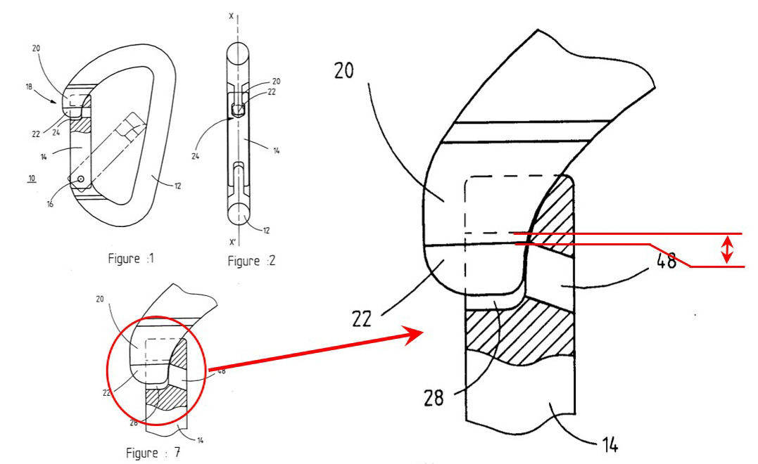
L’une de ces principales caractéristiques est le jeu fonctionnel situé au niveau de la fermeture du doigt. En escalade/alpinisme, et pour des raisons de sécurité, un mousqueton doit pouvoir continuer à s’ouvrir sous une charge de 80kg (poids d’un homme). Il existe donc dans leur conception un jeu fonctionnel qui permet toujours l’ouverture du doigt même lorsqu’il est chargé ainsi et qui autorise un léger déplacement d’une pièce par rapport à l’autre.
PHENOMENE DE FATIGUE
En parapente, nous sommes en permanence suspendus à nos connecteurs, mais cette charge est loin d’être constante. En effet, en vol nous sommes soumis à une multitude d’allègements et d’accélérations qui réduisent ou augmentent respectivement la charge appliquée sur les connecteurs. Cette variation de charge entraîne un léger déplacement alterné au niveau du jeu fonctionnel, et cette déformation engendre des contraintes mécaniques interne.
Cela induit un phénomène dit “de fatigue” correspondant au fait que les connecteurs sont sollicités alternativement en charge / décharge.
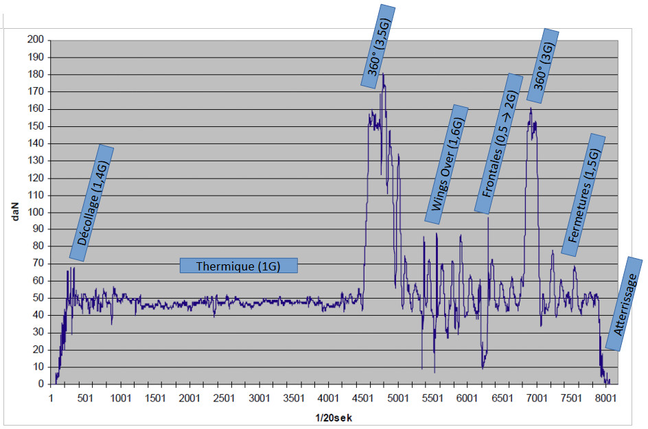
Mesures en vol droit stabilisé, spirale stabilisée, fermeture frontale, fermeture et wing-over (Source : DHV).
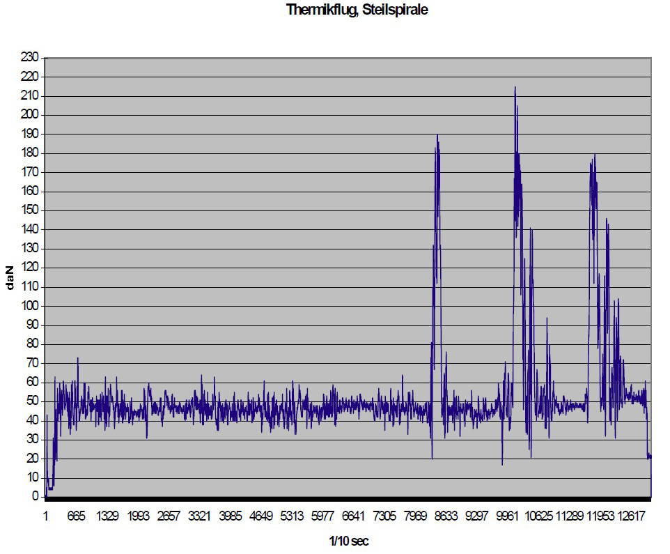
Mesures en thermique, puis en spirale stabilisée (Source : DHV)
Ce phénomène de fatigue est à prendre au sérieux, car il peut provoquer la rupture du mousqueton même si celui-ci n’a jamais subi de charge élevée durant son utilisation. Par ailleurs, les amorces de rupture sont internes et ne peuvent pas être détectées facilement. C’est pourquoi il est important de connaître l’historique des connecteurs, et de les changer avant qu’il ne soit trop tard … L’aluminium y est beaucoup plus sensible que l’acier en raison de sa structure cristalline interne. En revanche, d’autres connecteurs tels que les maillons rapides ou les connecteurs souples (Soft-links et autres) ne semblent « à priori » pas concernés par ce phénomène de fatigue.
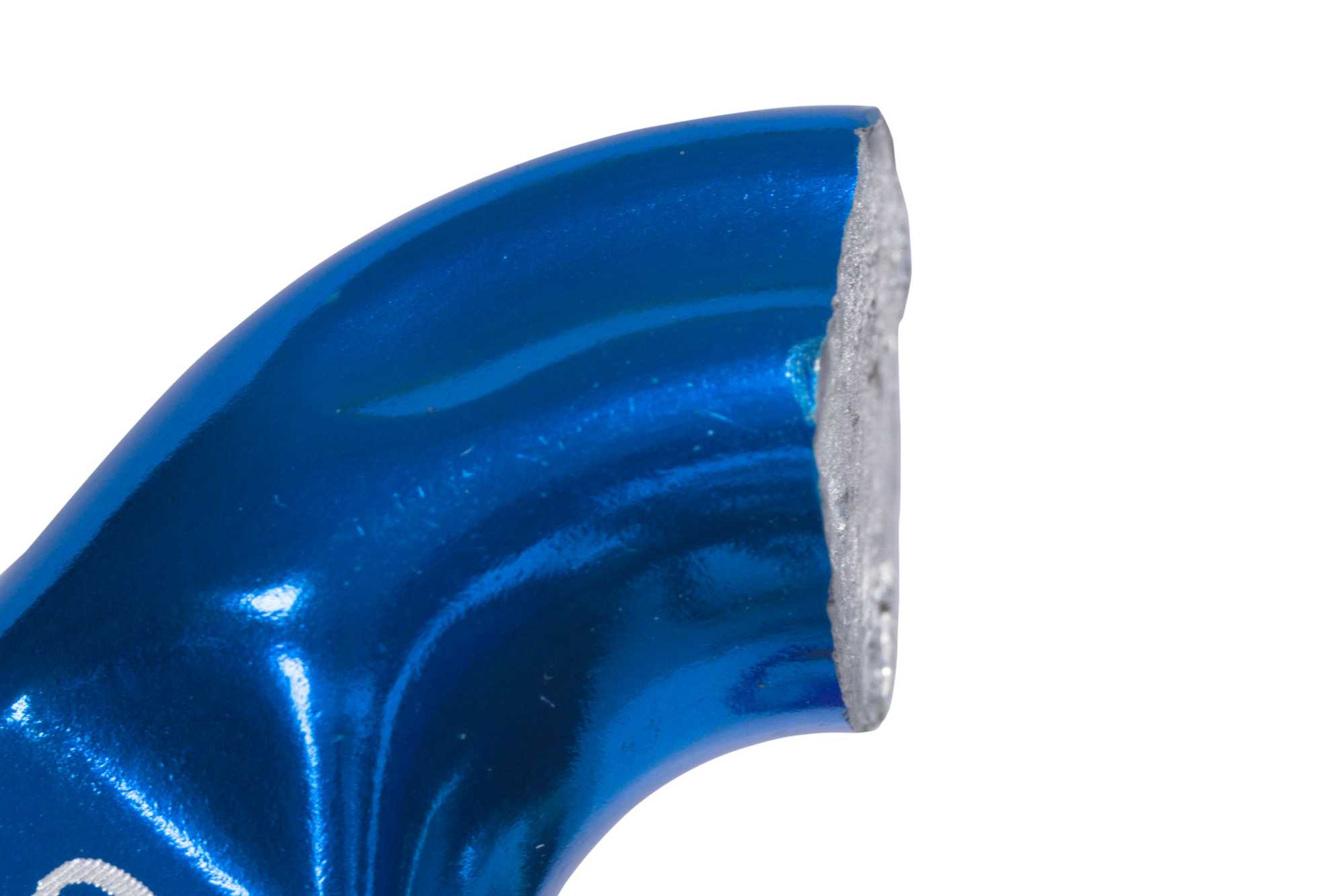
Rupture de fatigue
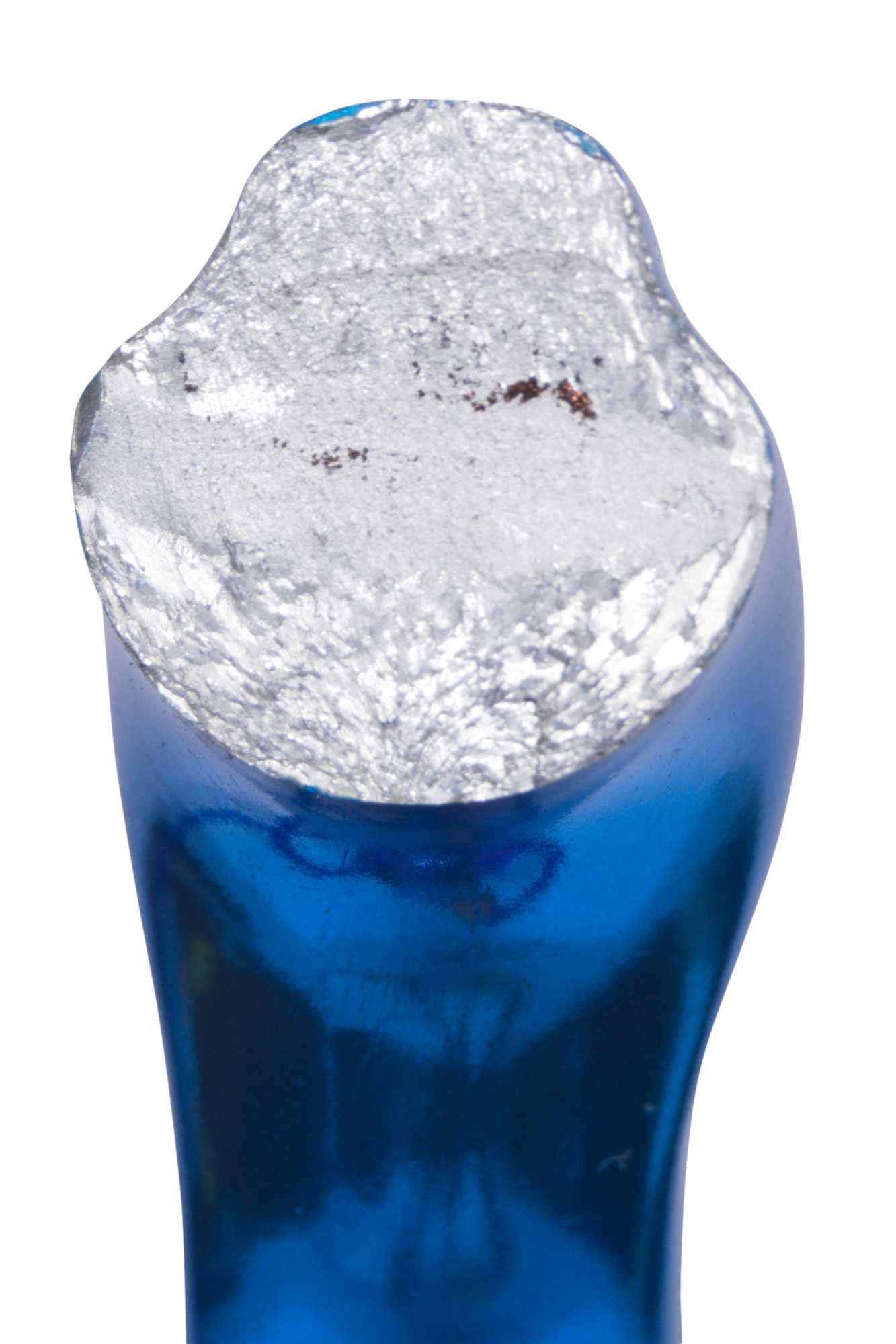
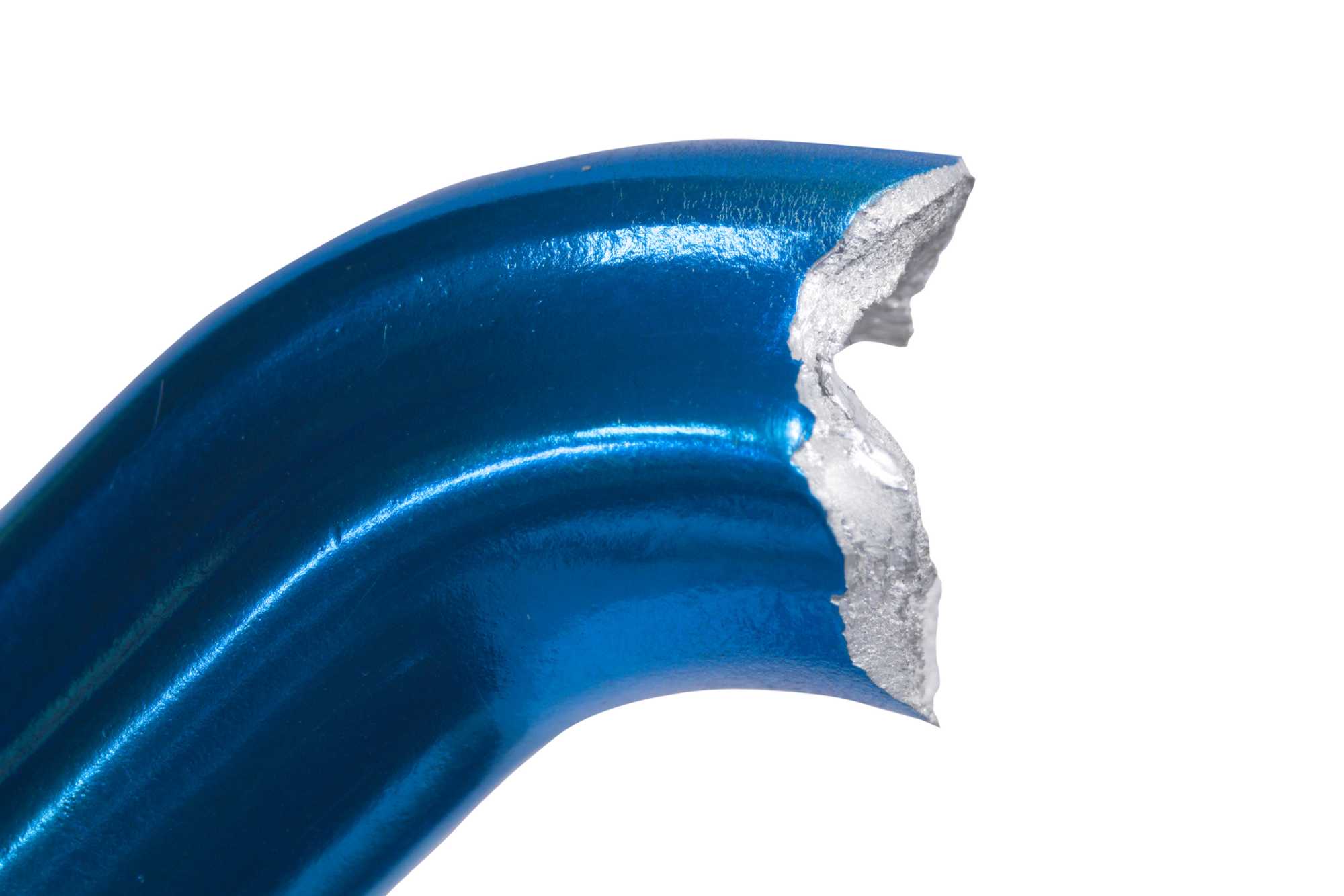
Rupture statique
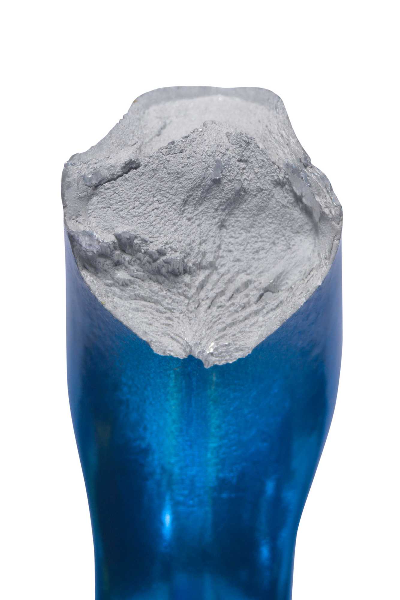
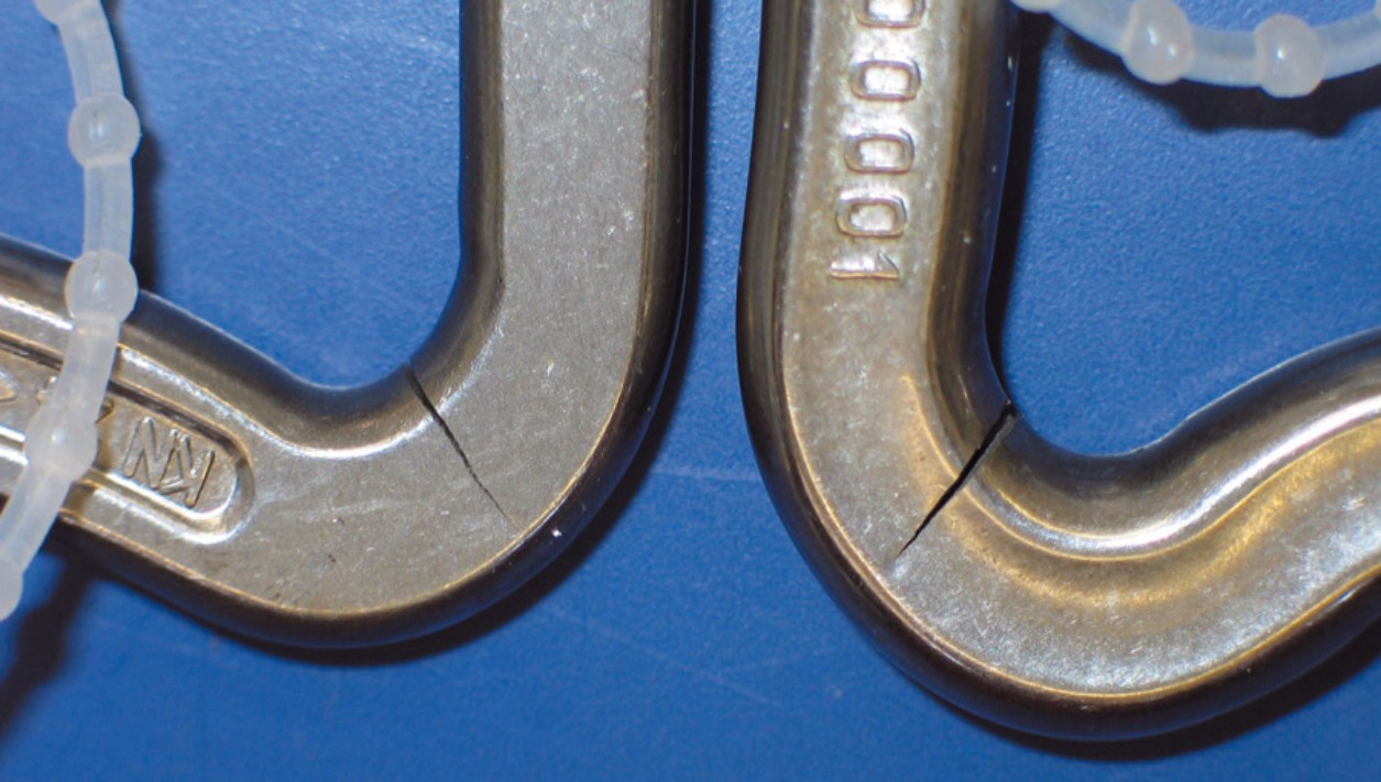
Amorce de rupture en fatigue
Les préconisations actuelles recommandent de changer les mousquetons automatiques tous les 5 ans ou toutes les 500h d’utilisation, que ce soit pour ceux en aluminium ou ceux en acier. Ces préconisations sont basées sur différents tests et analyses d’incidents qui ont pu être conduits jusqu’à présent sur des mousquetons automatiques (Voir Bibliographie).
En Septembre 2023, la PMA (Paraglider Manufacturers Association) a rédigé sur le sujet un « standard » (Eléments connecteurs pour le parapente) dans le but d’augmenter la sécurité des pilotes en proposant une validation de la résistance des connecteurs à la fatigue, avant leur mise sur le marché. Elle propose de simuler 5 ans ou 1000 heures d’utilisation (soit 2 millions de cycles charge / décharge) sur tous les types de connecteurs que nous pouvons être amenés à utiliser pour pratiquer le vol libre : maillons rapides, connecteurs souples, mousquetons automatiques, … Les valeurs Fmin et Fmax sont calculées, et adaptées au type de pratique (solo ou biplace). Une charge plus importante (Fmax extrem) est même insérée tous les 500 cycles, pour simuler quelques « manœuvres extrêmes » telles que des 360 engagés.
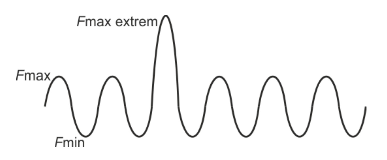
A la suite de ce test, si le connecteur conserve son intégrité et un fonctionnement correct, il doit encore résister à une charge statique pré-déterminée avant d’être considéré comme approuvé.
Ce « standard » n’est en rien une norme et n’impose aucune obligation stricte pour les fabricants, mais va certainement devenir la référence concernant la fiabilité des connecteurs disponibles sur le marché.
RESISTANCE – AXE DE TRAVAIL
Les connecteurs que nous utilisons sont tous extrêmement solides (Plus de détails dans : Réflexion sur la résistance des connecteurs).
Cette solidité à la rupture est bien évidemment liée au matériau utilisé, mais également à d’autres éléments de conception (dimensions, forme). Elle n’est pas non plus nécessairement homogène au sein de chaque connecteur.

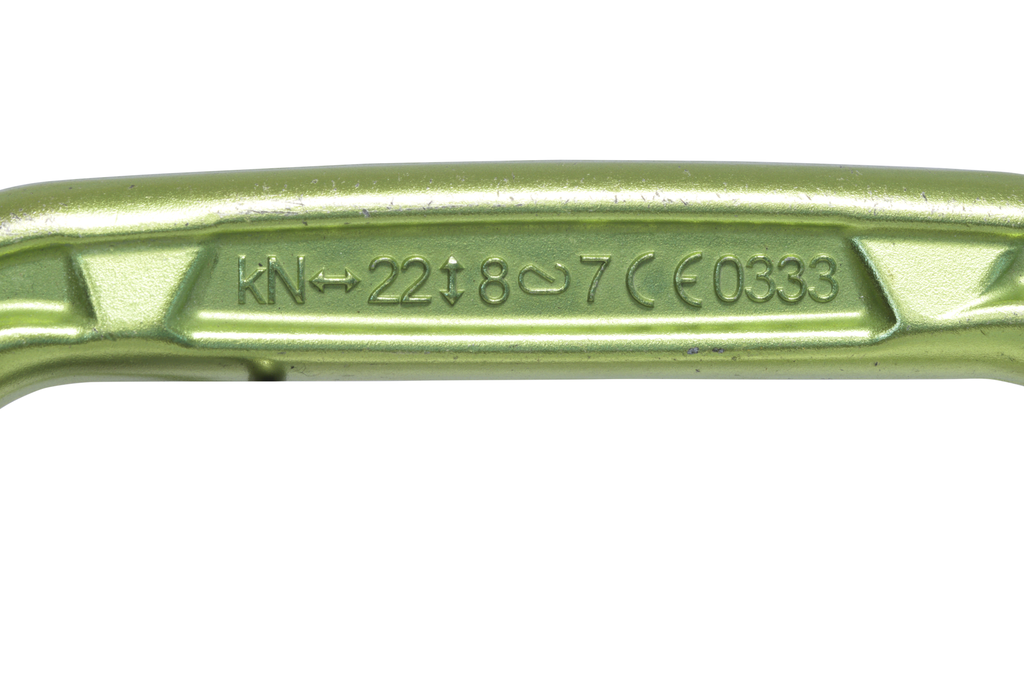
Si vous observez attentivement les mousquetons automatiques (de parapente ou d’escalade/alpinisme), vous trouverez normalement un marquage qui indique les différentes valeurs de résistance maximale du connecteur concerné, suivants différents axes de traction.
Ces valeurs peuvent être très différentes, et démontrent que chaque connecteur n’est pas forcément aussi solide quel que soit la manière dont il est utilisé. La résistance statique « en travers » (selon le petit axe) est ici de 8kN contre 22kN selon l’axe principal (grand axe), soit plus faible de 63 %.
22KN
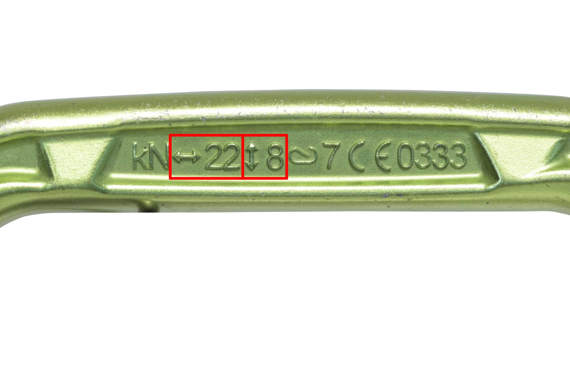
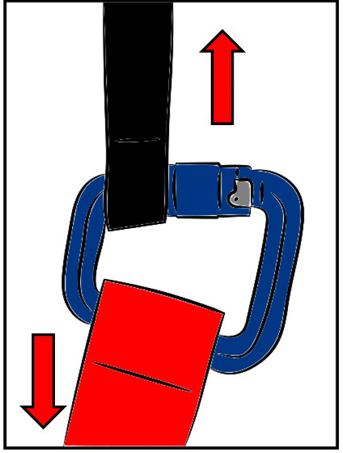
8KN
Les derniers essais de fatigue menés en interne conformément au standard de la PMA (voir plus haut) ont aboutis à des résultats très intéressants sur cet aspect de respect de l’axe de travail.
Sur les mousquetons automatiques testés, il est apparu que la position « désaxée » pouvait générer des résultats très différents en fonction du placement du connecteur sur les sangles.
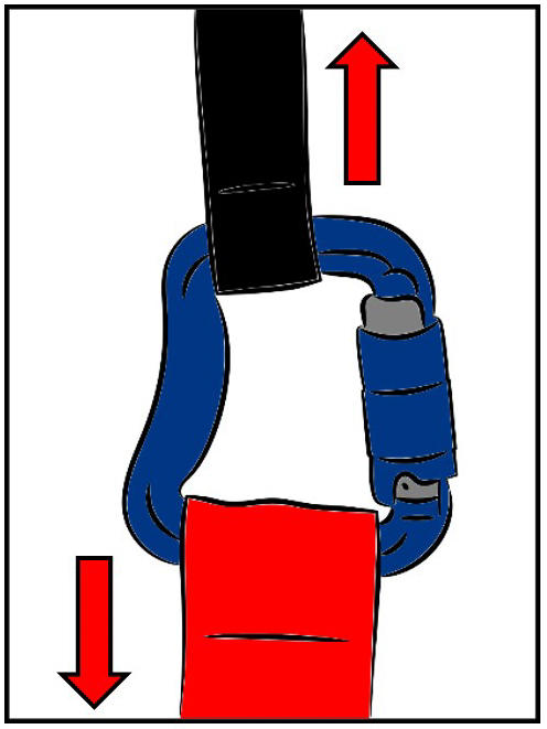
Lorsque le mousqueton auto est placé comme sur la figure 1, il arrive à passer les tests de fatigue soit 2 000 000 de cycles de charge/décharge entre 30kg et 100kg, mais il cède à 13KN en statique.
En revanche, lorsqu’il est placé comme sur la figure 2 il cède au bout de 158 000 cycles. Ce qui représente seulement 8 % de la tenue en fatigue exigée par le standard de la PMA. Si on ramène ce chiffre en durée théorique (pour 200h de vol/an) le mousqueton tiendrait moins de 5 mois ou 80h.
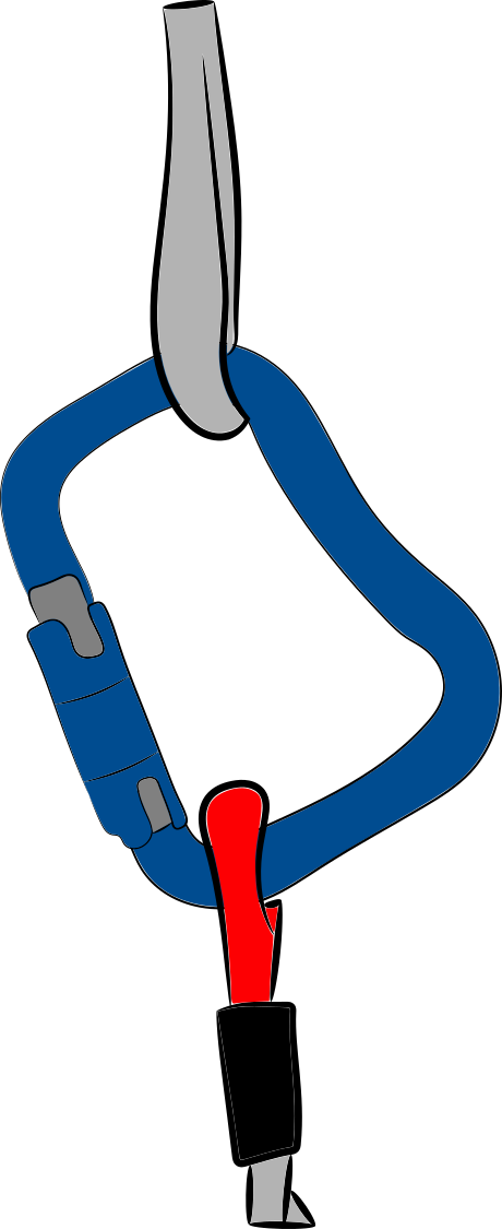
Figure 1
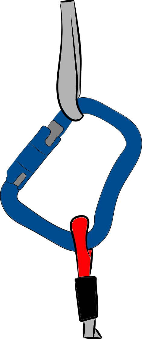
Figure 2
Vous comprenez bien qu’il est primordial de faire travailler ce type de connecteur (mousquetons automatiques) selon leur axe principal, pour conserver la meilleure résistance à la rupture possible, que ce soit en statique ou en fatigue. Toute charge de travail appliquée en dehors de cet axe théorique peut fragiliser de manière dramatique le connecteur.
Tous les types de connecteurs ne sont pas forcément concernés par cette contrainte. C’est le cas de la plupart des connecteurs souples, qui peuvent encaisser la même charge quelles que soit leur position dans l’assemblage.
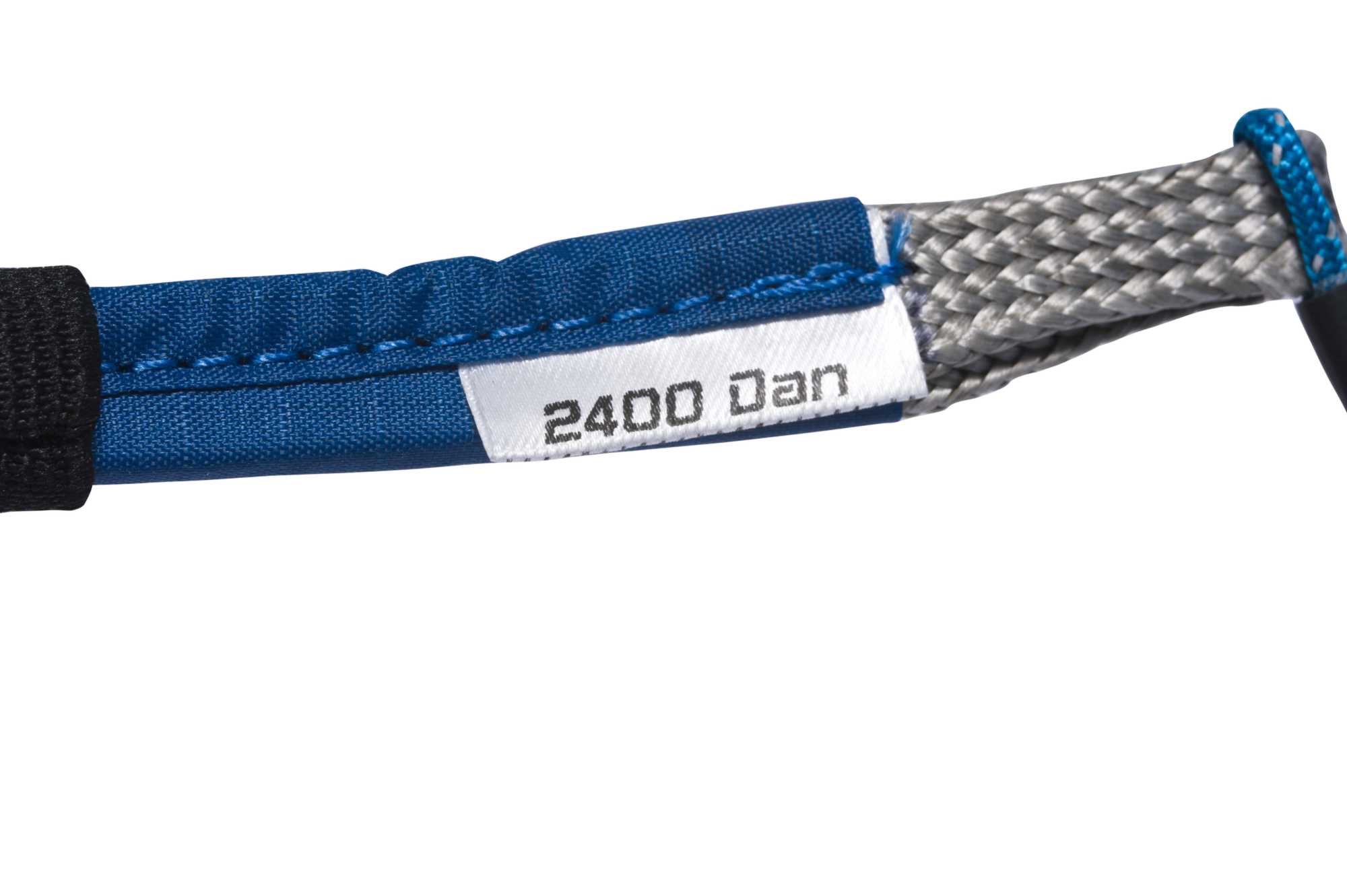
Vous trouverez donc normalement simplement la valeur maxi de résistance admissible sur l’étiquette qui les accompagne. Les tests réalisés en fatigue ne montrent pas non plus de fragilité sur ce type de connecteur.
Comment faire pour garantir le respect de cet axe de travail principal ?
Il existe pour cela plusieurs solutions :
– La première vise à maintenir en place le connecteur à l’aide de joints toriques pour maintenir les sangles à leur place sur le connecteur. Cela permet d’éviter une rotation intempestive du mousqueton lorsque la charge est faible, mais en cas de charge importante le joint torique peut tout de même glisser et laisser la sangle se déplacer. C’est d’autant plus vrai lorsque la sangle est bien moins large que le mousqueton.
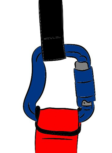

– La seconde solution consiste à sélectionner un connecteur (mousqueton auto ou autre) qui soit en parfaite adéquation dimensionnelle avec les sangles qu’il relie. De cette manière, les sangles viendront naturellement se placer au bon endroit sur le connecteur et lui permettront de toujours travailler correctement. L’utilisation d’un connecteur étroit pour une sangle large peut sembler être une bonne idée pour « coincer » la sangle, mais dans ce cas c’est cette dernière qui ne travaillera pas correctement et qui verra peut-être aussi ses capacités de résistance amoindries.

Le très large choix disponible aujourd’hui sur le marché permet de trouver des connecteurs de toutes sortes pour s’adapter à la plupart des configurations. Leur conception peut même solutionner plusieurs problématiques simultanément, comme le Pin-Lock (Finsterwalder) qui intègre un système anti-retournement et dont la forme en lyre lui permet également de ne pas travailler en fatigue. Ils sont donnés par Finsterwalder pour une durée de vie de 8 ans en utilisation solo, sans limitation d’heures d’utilisation !
Les connecteurs souples sont également intéressants car ils ont la faculté de s’adapter dimensionnellement aux sangles, et ne sont pas impactés par le phénomène de fatigue.
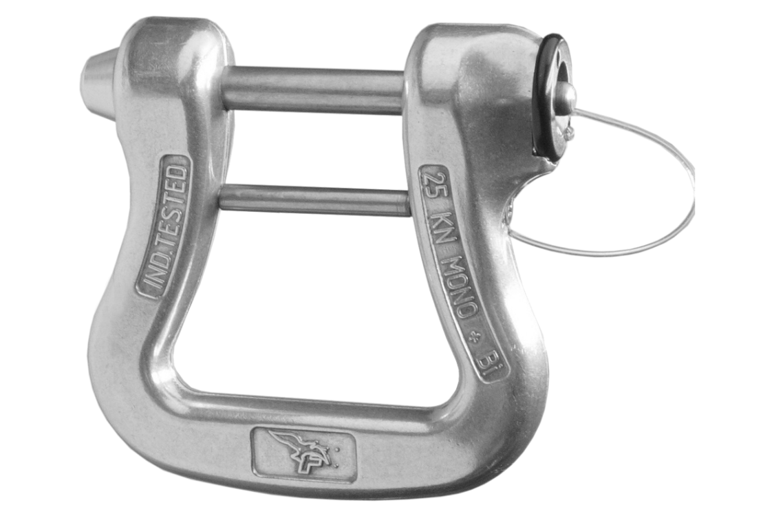
Pin-Locks (Finsterwalder)
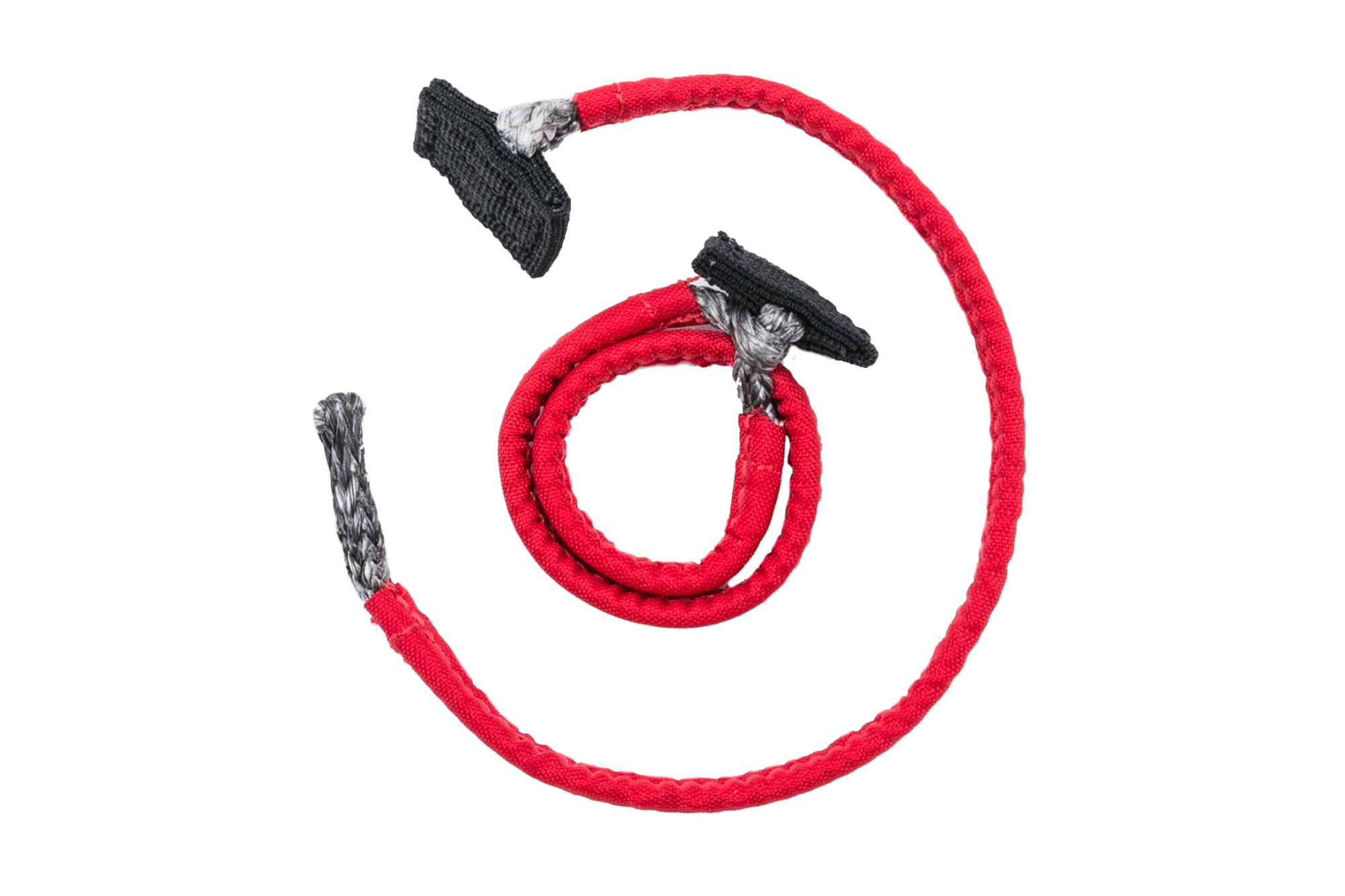
Connecteurs souples
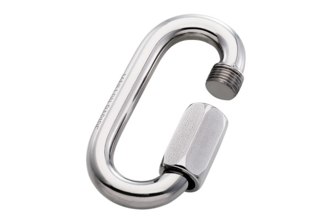
Maillons à vis (Péguet)
La résistance maximale des mousquetons est donc obtenue lorsque la charge de travail est appliquée sur l’axe principal. Mais il faut aussi que le doigt du mousqueton soit correctement fermé. Dans le cas contraire, la résistance est fortement réduite comme le montre la 3ème valeur gravée.
Pour éviter ce genre de désagrément, les mousquetons sont dits « automatiques » car ils sont équipés d’un système de verrouillage qui s’enclenche automatiquement lorsque l’on relâche le doigt d’ouverture, sans aucune action de la part de l’utilisateur.
En revanche, pour éviter toute ouverture intempestive qui réduirait la résistance, l’utilisateur doit procéder à une ou plusieurs actions déterminées afin de libérer le doigt. Cela peut passer par un quart de tour sur le doigt avant de le pousser (2 temps), ou bien nécessiter un petit déplacement de la bague avant de lui appliquer la quart de tour (3 temps). Ces systèmes peuvent parfois sembler un peu « compliqués » et nécessiter les 2 mains pour réussir à ouvrir le mousqueton, mais limitent considérablement les risques de se retrouver en vol avec un mousqueton doigt ouvert qui aura alors perdu plus de la moitié de sa résistance.

“Ouverture 2 temps”

“Ouverture 3 temps”
Ce système de verrouillage peut également être manuel, avec une virole par exemple que l’utilisateur doit visser pour verrouiller le mousqueton. Si ce dernier n’effectue pas l’action de visser la virole, le mousqueton n’est pas totalement verrouillé et le doigt pourrait s’ouvrir inopinément, en l’accrochant par exemple.

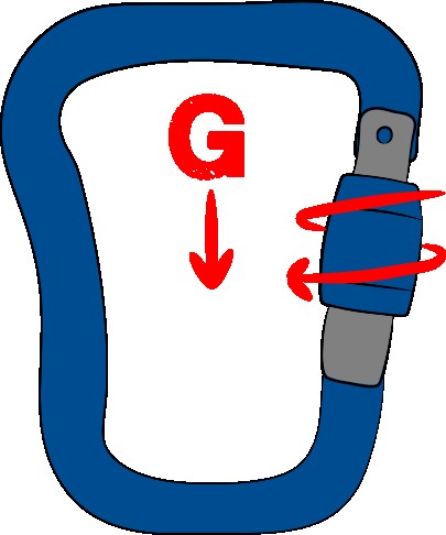
Son ouverture passe aussi par une action manuelle de l’utilisateur, en dévissant la virole et en ouvrant le doigt. Ce genre de verrouillage n’est pas totalement sûr, car les diverses vibrations qu’il peut subir (en vol, dans le coffre de la voiture, …) peuvent finir par dévisser la virole et laisser possible l’ouverture du doigt. Si vous utilisez ce genre de mousqueton (en vol montagne par exemple), nous recommandons de placer le mousqueton de telle sorte que le verrouillage de la virole se fasse vers le bas. En cas de vibration, la gravité aidera à toujours ramener la virole dans sa position verrouillée. Dans l’autre sens, la gravité pourra faciliter le dévissage en combinaison avec les vibrations.
D’autres systèmes peuvent exister, mais ce sont là les principaux que nous allons trouver sur les mousquetons disponibles dans le milieu du parapente.
SPECIFICITES LIEES AU PARACHUTE DE SECOURS
Comme nous venons de le voir, un connecteur est conçu pour relier 2 éléments (sangles ou autres boucles). Normalement la charge appliquée se fera selon l’axe formé par les 2 éléments reliés.
Les connecteurs vus précédemment peuvent donc tout à fait convenir (sous réserve d’une résistance nominale suffisante) pour connecter les élévateurs de secours à la sellette, ou le parachute aux élévateurs.
La grande majorité du temps, l’ensemble de la chaîne de déploiement du parachute de secours est cachée (à l’exception de la poignée !) pour protéger ces différents éléments des diverses agressions extérieures (frottements, Uvs, …) ou d’éventuelles mauvaises manipulations, et ce afin de garantir un fonctionnement stable et fiable dans le temps. Il est donc compliqué de vérifier de manière automatique si tout est bien en ordre.
Concernant le parachute de secours, il est donc recommandé d’utiliser des connecteurs :
– adaptés en termes de forme pour respecter l’axe de travail des sangles
– le cas échéant, verrouillés à l’aide de joints toriques
– dont le système de fermeture et de verrouillage n’est pas sensible aux phénomènes de vibrations ou autres qui pourraient les relâcher à la longue
– ne sont pas trop sensibles à la direction de la charge appliquée (résistance multidirectionnelle)
Il est également possible d’envisager de connecter directement les sangles entre elles à l’aide d’un nœud en « tête d’alouette », et de s’affranchir ainsi d’un connecteur et des contraintes qu’il peut entraîner. Malgré la mauvaise image que ce nœud peut encore avoir, il est très performant dès lors qu’il est exécuté correctement (comme tous les nœuds!). Il faut veiller à ce que les sangles reliées soient maintenues le plus à plat possible, et que le nœud ne puisse pas se desserrer ni laisser la possibilité d’avoir un mouvement relatif entre les sangles. En effet, il existe un risque important de rupture si la mise en tension se fait à la suite d’un long glissement qui induira des frottements et donc de l’échauffement.

S’il n’y a pas de mouvement important, aucun risque d’échauffement … D’ailleurs, toutes les connexions des suspentes de votre voile sont réalisées de cette manière, ainsi que toutes les connexions entre les suspentes hautes, moyennes, basses, etc … C’est donc bien que ça marche et que c’est fiable !
Dans l’hypothèse où la sellette ne dispose pas de sangles d’épaules, ou que celles-ci ne sont pas équipées de points d’ancrage pour le secours, la seule solution consiste à connecter les élévateurs de secours aux points d’ancrage principaux de la sellette où se trouve déjà les connecteurs reliant les élévateurs de la voile. Deux options pour réaliser la connexion :
– Ajouter l’élévateur de secours dans le même connecteur qui relie déjà la voile principale.
Il est possible d’envisager cette solution s’il reste assez de place dans le connecteur. Lorsque le secours est tiré, la charge passe normalement de l’élévateur de la voile à celui du secours au moment où celui-ci commence sa prise en charge. La voile quand à elle doit normalement être neutralisée et ne plus avoir d’influence sur le connecteur.
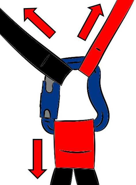
Néanmoins, en fonction du connecteur et des sangles (formes, dimensions), le placement de l’élévateur de secours peut se faire de travers et modifier l’axe de travail : en cas d’effet miroir ou si celui-ci venait à se coincer dans la virole de verrouillage par exemple.
Il est donc préférable d’utiliser dans ce cas des connecteurs avec des capacités de résistance multi-axiales (Péguet, connecteurs souples), ou à emporter un système de coupe suspente pour pouvoir sectionner un élévateur de la voile si celle-ci se remettait à voler après déploiement du secours. Avec un secours hémisphérique en effet-miroir, l’angle entre les élévateurs est de l’ordre de 90°. Avec un Rogallo (qui a une vitesse propre), il est possible d’arriver à 180° et donc d’induire ces efforts dans le petit axe du connecteur, le plus faible.

– Ajouter un autre connecteur permettant de séparer l’attache de la voile principale et du secours.
En cas de connexion des 2 élévateurs sur le même point d’ancrage avec 2 connecteurs séparés, il se peut aussi qu’un effet-miroir vienne générer des efforts opposés sur le point d’ancrage. Dans cette situation, c’est la construction même du point d’ancrage qui déterminera la solidité de l’ensemble.
Même remarque que précédemment, l’emport d’un coupe suspente est recommandé pour pouvoir couper un élévateur de la voile dans le cas où celle-ci revolerai et augmenterait les efforts générés.
