Thinking about ... connectors (Updated Jan. 2024)
This update takes up the main points of the previous version, adding to and updating the current state of knowledge on connectors, concerning their design, stresses, working axes, different assemblies, etc...
The Technical Reflexion on " Connector strength" provides further information on the nominal strength required of connectors.
First and foremost, it's important to know that there are currently no standards governing the strength, shape or operating principle of our connectors, as is the case for climbing and mountaineering carabiners. So it's up to each and every one of us to make our own equipment, and in particular to choose our connectors with full knowledge of the facts, to ensure maximum safety in our practice.
Available connectors come in a variety of shapes, materials, locking systems, etc. Each solution has its own advantages and constraints, and their use will depend on the specific application.
DESIGN OF AUTOMATIC CARABINERS
Today, the vast majority of harnesses are equipped with automatic aluminum carabiners. They are light, easy to handle and seem to represent the ideal solution for connecting our paragliders.
Let's take a look at the design of these self-closing carabiners.
Their design is directly linked to that of climbing and mountaineering carabiners, and generally takes up all of their functions.
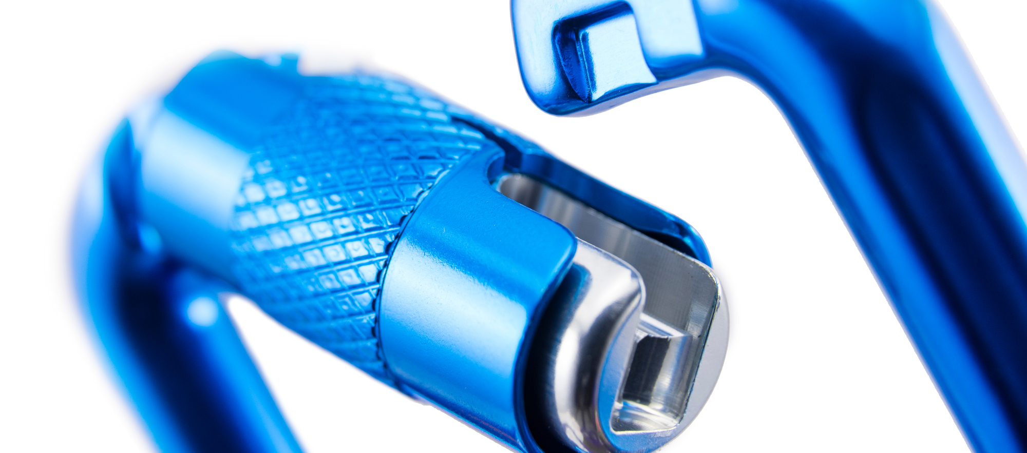
In simple terms, this is a metal ring with a hinged part that can be opened and closed to insert all kinds of connecting loops. This hinged part, known as the "finger", can be fitted with a locking system to prevent accidental opening.

But regardless of which locking system is used, the design of these carabiners is exactly the same as for climbing and mountaineering carabiners. In fact, the manufacturers of both are often the same.
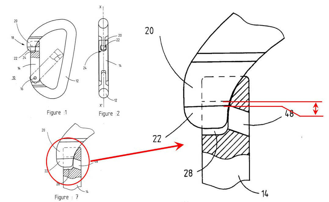
One of its main features is the functional clearance at the finger closure. In climbing/mountaineering, and for safety reasons, a carabiner must continue to open under a load of 80kg (one man's weight). Their design therefore incorporates a functional gap that allows the finger to remain open even when loaded, and allows a slight displacement of one part in relation to the other.
FATIGUE PHENOMENON
In paragliding, we are constantly suspended from our connectors, but this load is far from constant. In flight, we are subjected to a multitude of lightenings and accelerations, which respectively reduce or increase the load applied to the connectors. This variation in load leads to a slight alternating displacement in the functional gap, and this deformation generates internal mechanical stresses.
This leads to a phenomenon known as "fatigue", corresponding to the fact that connectors are alternately loaded and unloaded.
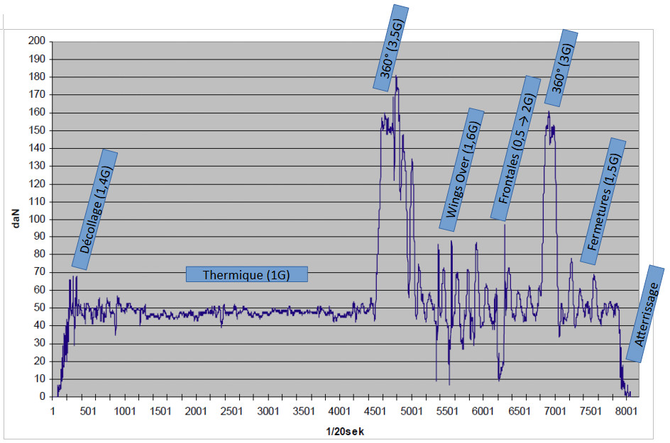
Measurements in stabilized straight flight, stabilized spiral, frontal closure, closure and wing-over (Source: DHV).
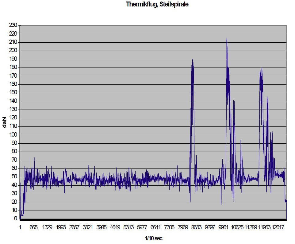
Measurements in thermal, then in stabilized spiral (Source: DHV)
This fatigue phenomenon must be taken seriously, as it can cause the carabiner to break even if it has never been subjected to a high load during use. Furthermore, breakage initiators are internal and cannot be easily detected. That's why it's important to know the history of your connectors, and to change them before it's too late... Aluminum is much more susceptible than steel, due to its internal crystalline structure. On the other hand, other connectors such as quick-links or soft-links do not seem to be affected by fatigue "a priori".
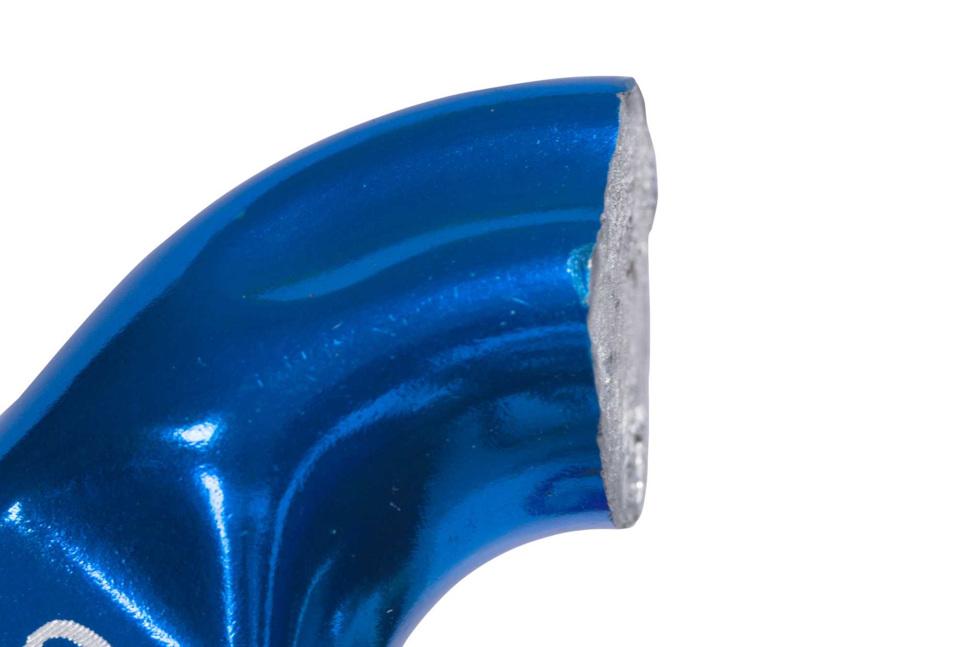
Fatigue rupture
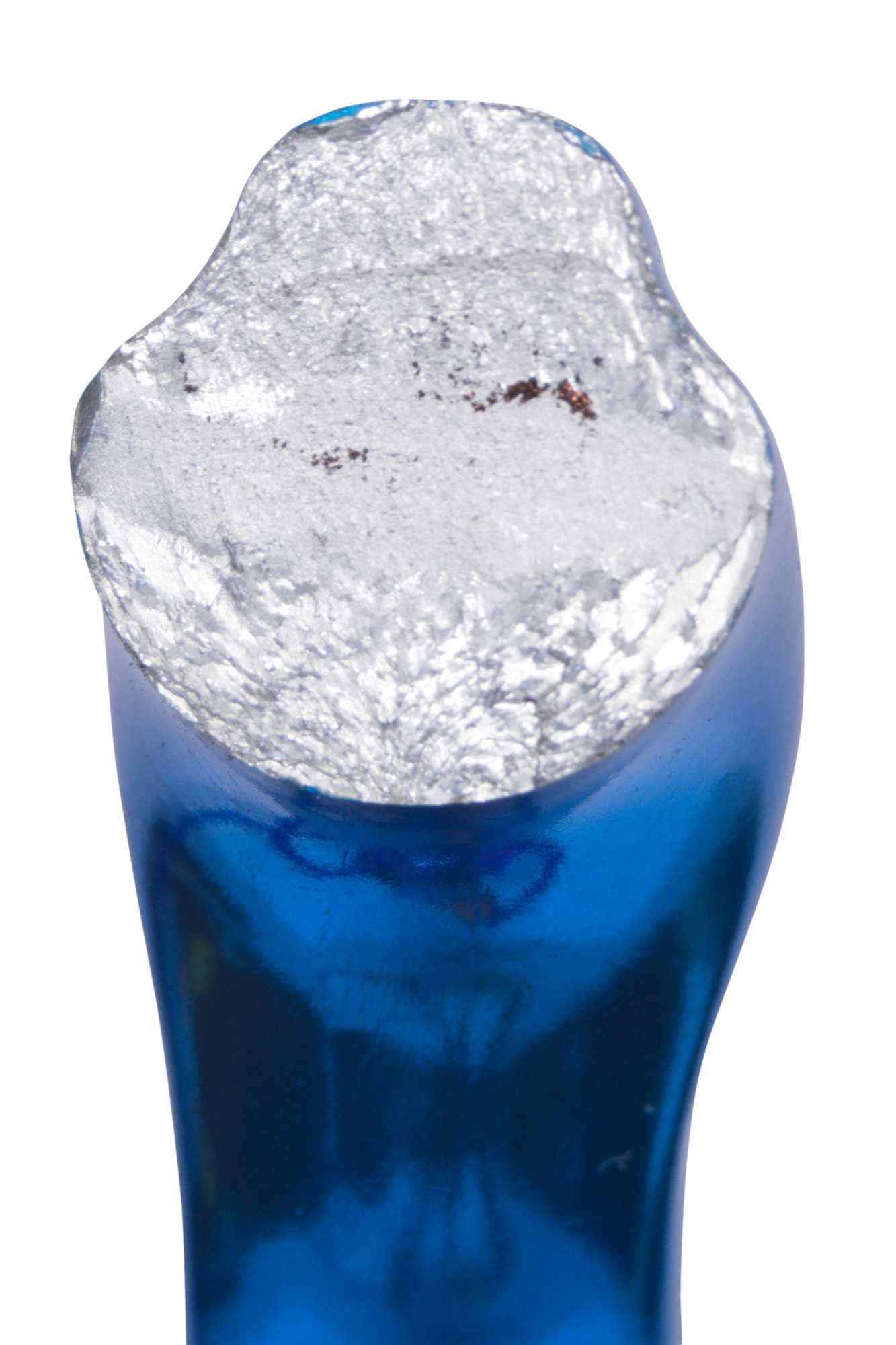
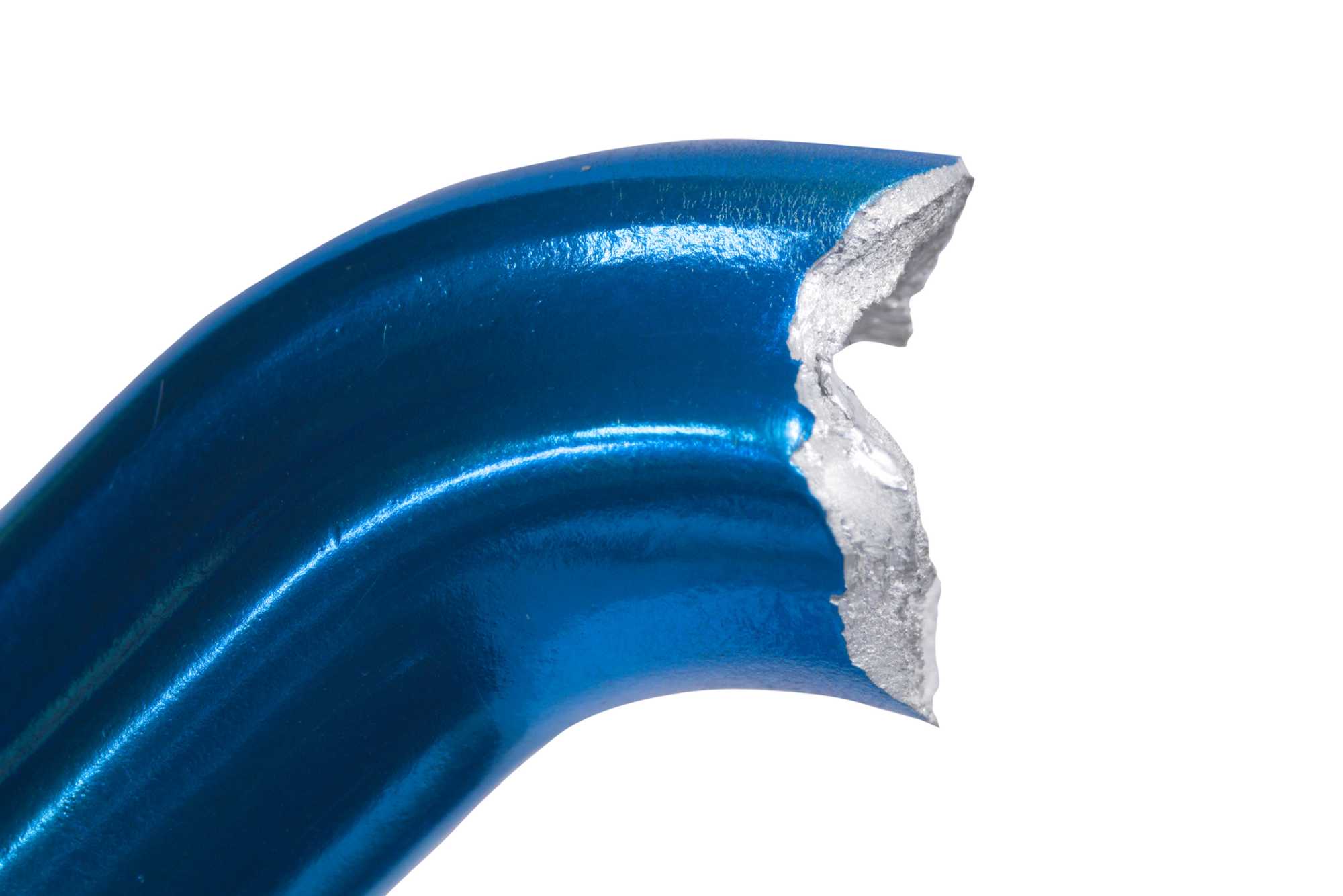
Static fracture
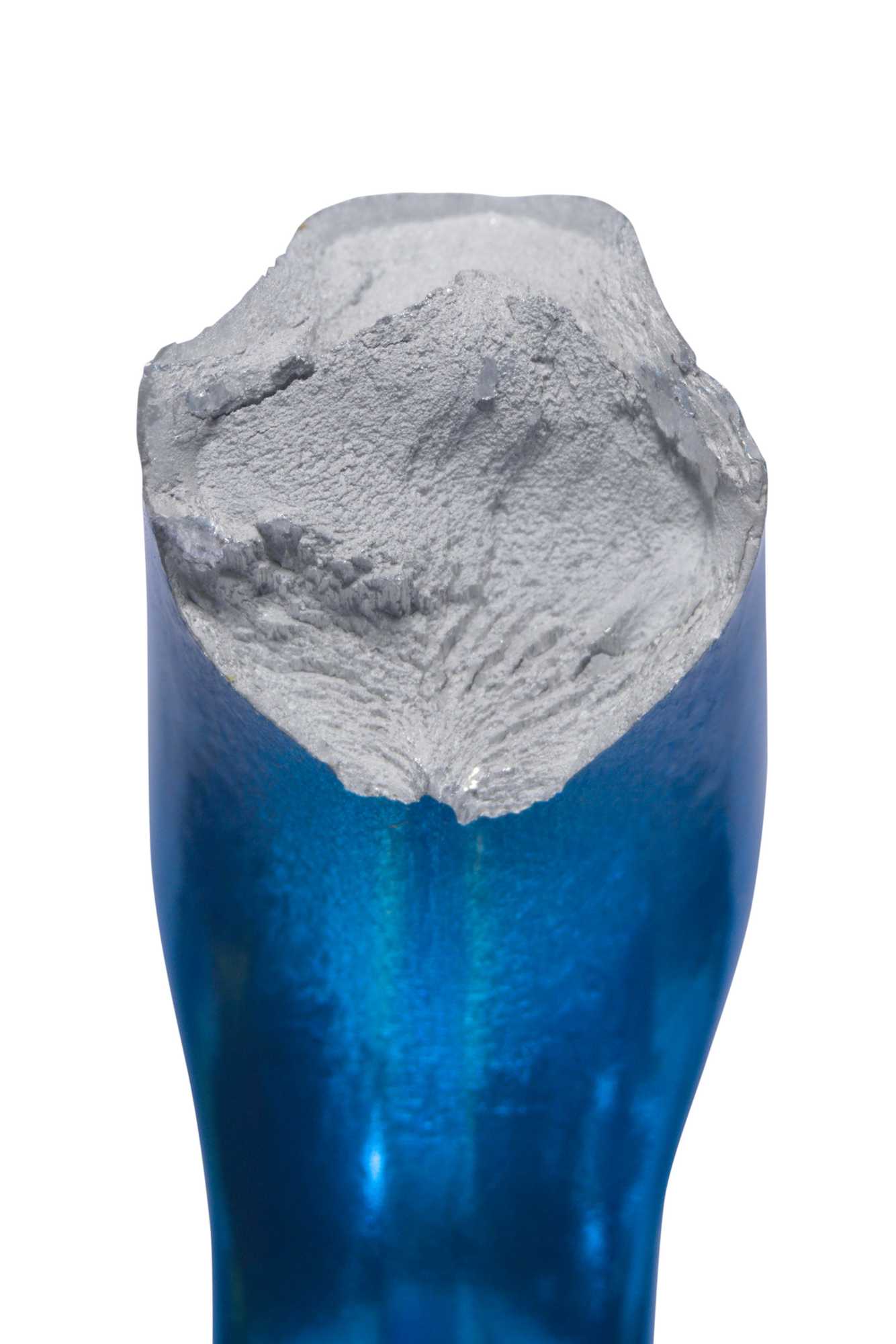
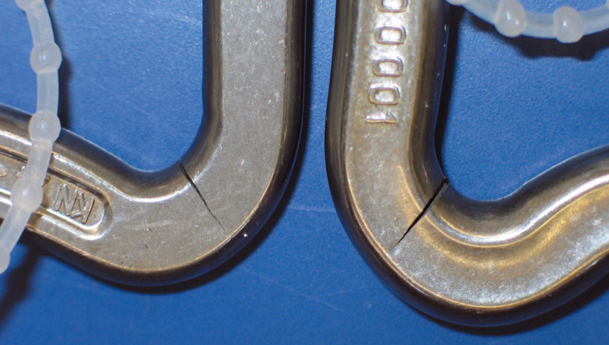
Fatigue fracture initiation
Current recommendations call for automatic carabiners to be changed every 5 years or 500 hours of use, whether in aluminum or steel. These recommendations are based on various tests and incident analyses carried out to date on automatic carabiners (see Bibliography).
In September 2023, the PMA (Paraglider Manufacturers Association) drew up a "standard" on the subject(Connecting elements for paragliding) with the aim of increasing pilot safety by proposing a validation of connector fatigue resistance, before they are put on the market. It simulates 5 years or 1,000 hours of use (i.e. 2 million load/unload cycles) on all the types of connectors we may use in free flight: quick links, flexible connectors, automatic carabiners, etc. Fmin and Fmax values are calculated, and adapted to the type of practice (solo or tandem). A higher load (Fmax extrem) is even inserted every 500 cycles, to simulate some "extreme maneuvers" such as high-load spirals.
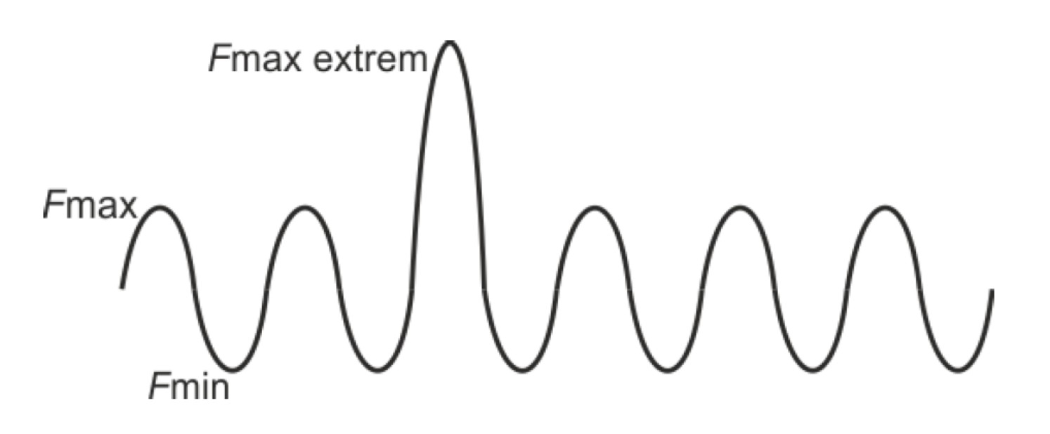
Following this test, if the connector retains its integrity and correct operation, it must still withstand a pre-determined static load before being considered approved.
This "standard" is by no means a norm and imposes no strict obligations on manufacturers, but it is certain to become the benchmark for the reliability of connectors available on the market.
RESISTANCE - AXIS OF WORK
The connectors we use are all extremely robust (more details in: Reflexion on connector resistance).
This breaking strength is obviously linked to the material used, but also to other design elements (dimensions, shape). Nor is it necessarily homogeneous within each connector.

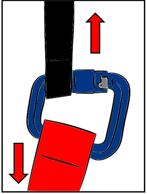
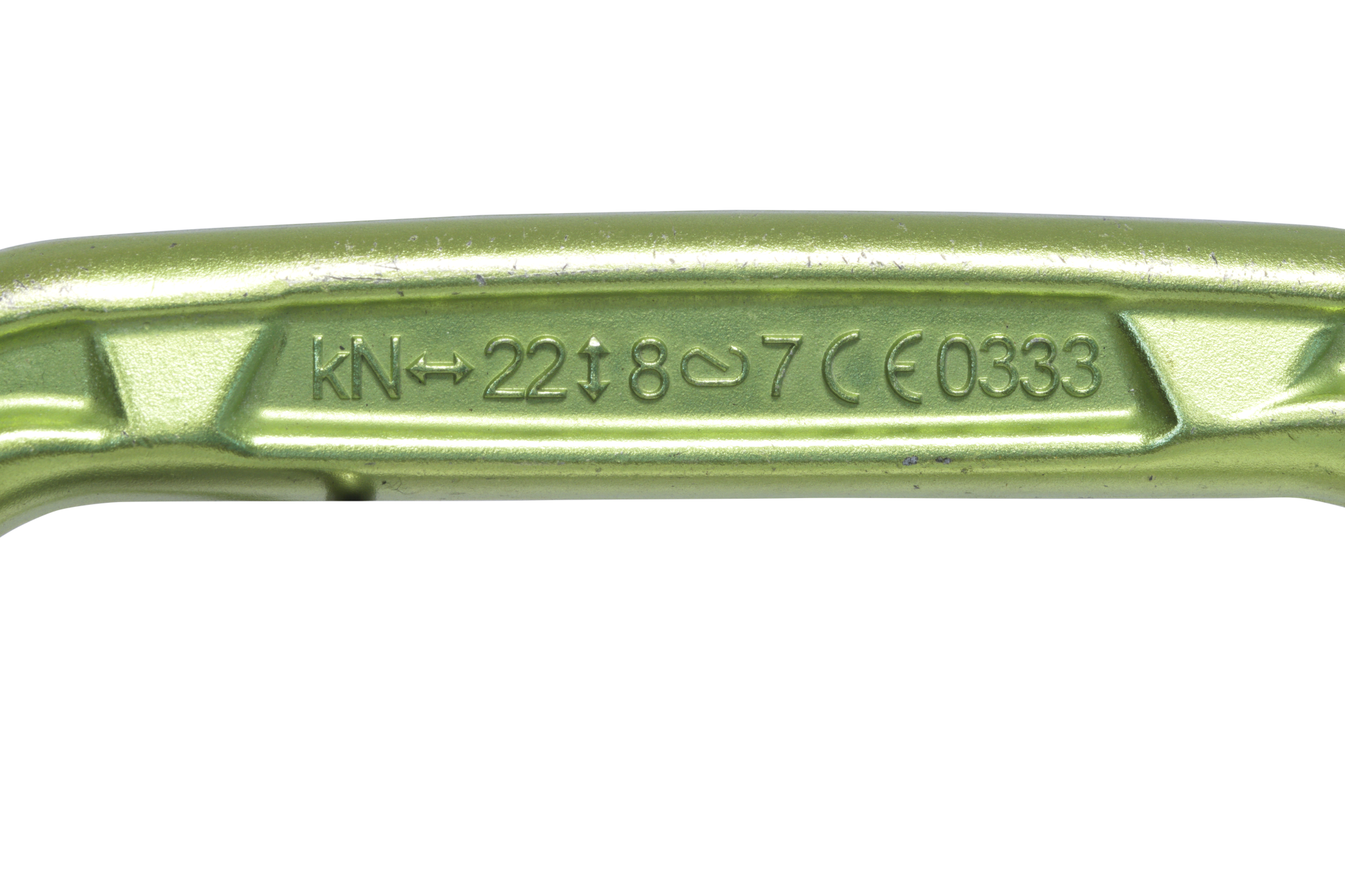
If you look closely at automatic carabiners (for paragliding or climbing/mountaineering), you'll normally find a marking indicating the different maximum strength values of the connector concerned, following different axes of pull.
These values can be very different, and show that not every connector is equally strong, however it's used. Static strength "across" (along the minor axis) here is 8kN versus 22kN along the major axis (major axis), i.e. 63% lower.
22kN
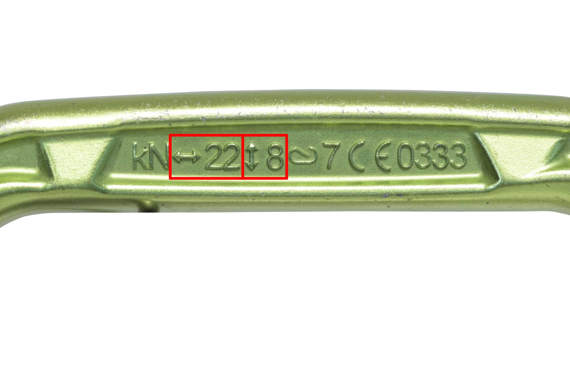
8kN
The latest fatigue tests carried out in-house in accordance with the PMA standard (see above) have produced some very interesting results in this respect.
On the automatic carabiners tested, it appeared that the "off-axis" position could generate very different results depending on the connector's placement on the straps.
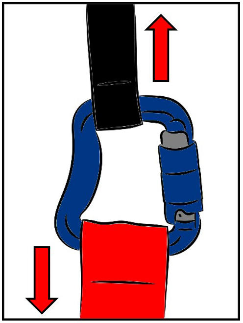
When the carabiner is positioned as shown in Figure 1, it passes the fatigue test of 2,000,000 load/unload cycles between 30kg and 100kg, but fails at 13kN static.
However, when positioned as shown in Figure 2, it fails after 158,000 cycles. This represents just 8% of the fatigue life required by the PMA standard. If we translate this figure into theoretical duration (for 200h of flight/year), the carabiner would last less than 5 months or 80h.
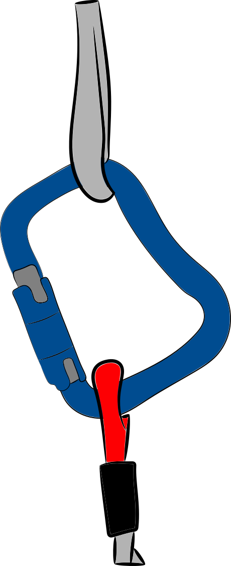
Figure 1
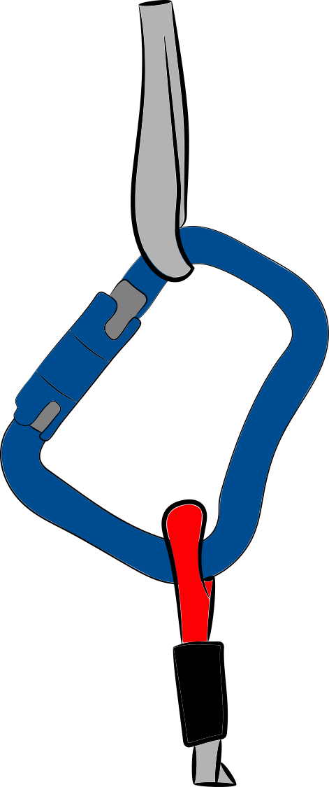
Figure 2
As you can see, it's vital to work this type of connector (automatic carabiners) along their main axis, to maintain the best possible resistance to breakage, whether static or fatigue. Any workload applied outside this theoretical axis can dramatically weaken the connector.
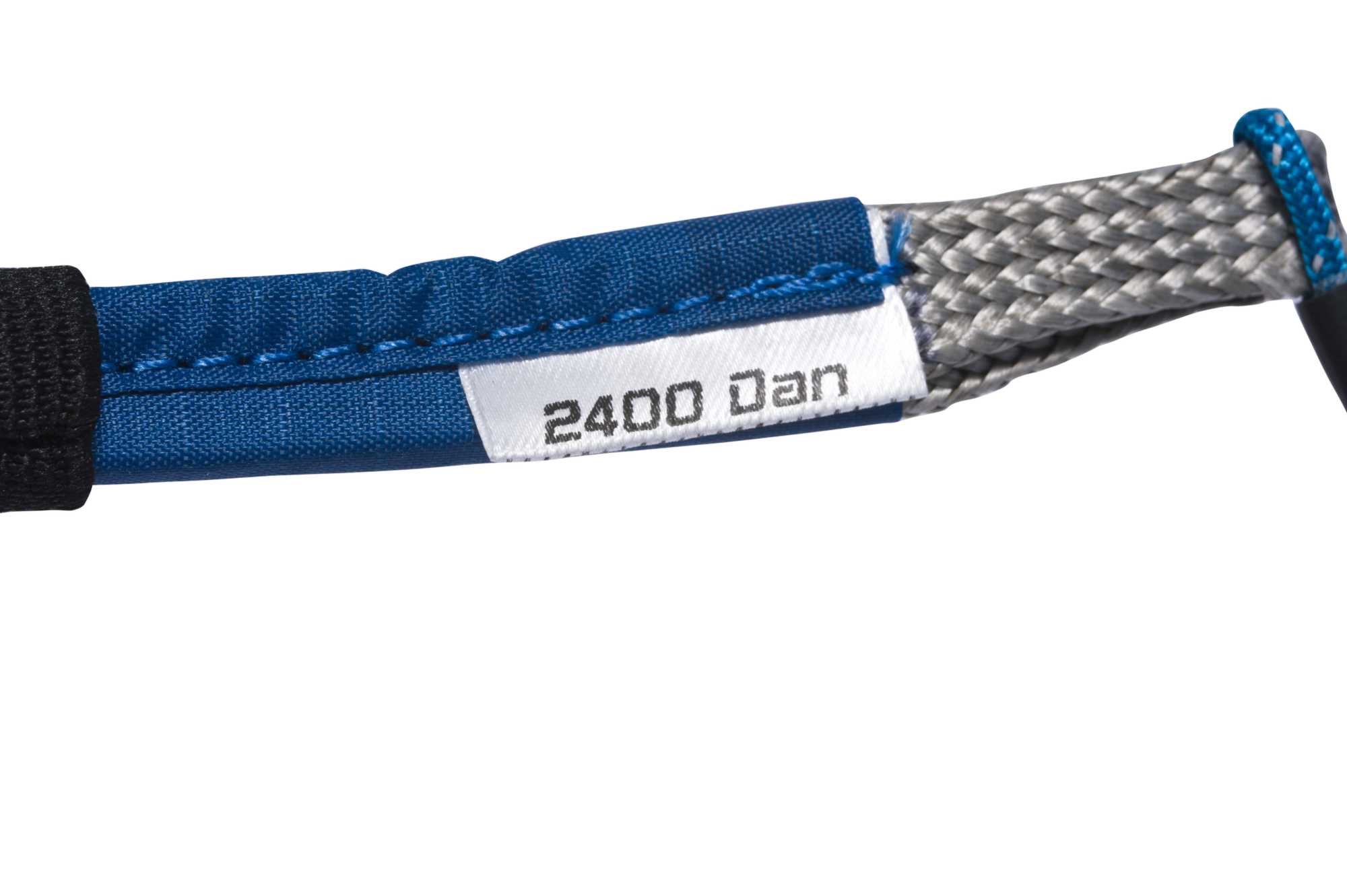
Not all connector types are affected by this constraint. This is the case for most flexible connectors, which can take the same load whatever their position in the assembly.
You will therefore normally simply find the maximum permissible resistance value on the label that accompanies them. Fatigue tests also show no fragility in this type of connector.
How can we ensure that this main focus of our work is respected?
There are several solutions for this:
- The first is to hold the connector in place, using O-rings to keep the straps in place on the connector. This prevents unintentional rotation of the carabiner under light loads, but under heavy loads the O-ring can still slip, allowing the sling to move. This is especially true when the sling is much narrower than the carabiner.
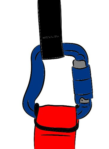

- The second solution is to select a connector (carabiner or other) that is perfectly dimensionally matched to the straps it connects. This way, the straps will naturally come to rest in the right place on the connector, enabling it to work properly at all times. Using a narrow connector for a wide webbing may seem like a good idea to "wedge" the webbing, but in this case it's the webbing itself that won't work properly, and may also see its resistance capabilities reduced.

The very wide choice available on the market today means that connectors of all kinds can be found to suit most configurations. Their design can even solve several problems simultaneously, like the Pin-Lock (Finsterwalder), which incorporates an anti-twist system and whose lyra shape also means it doesn't work in fatigue. Finsterwalder gives them an 8-year life expectancy in solo use, with no limit on hours of use!
Flexible connectors are also of interest, as they can adapt dimensionally to the straps, and are not affected by fatigue.
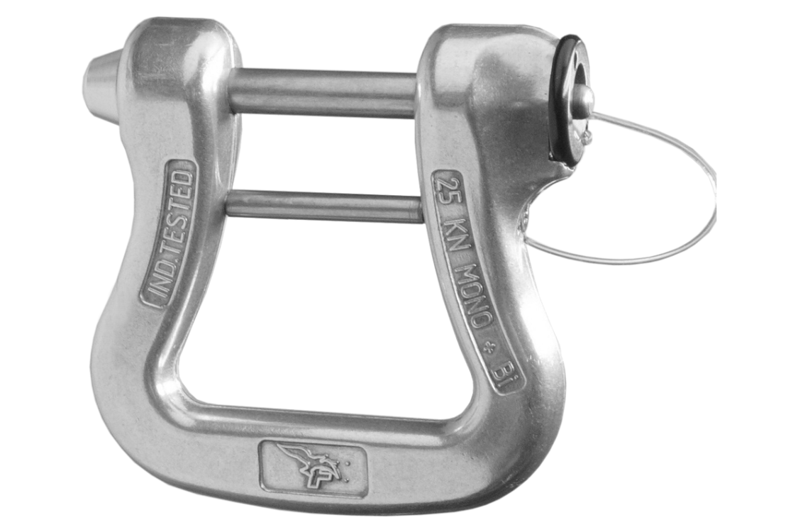
Pin-Locks (Finsterwalder)
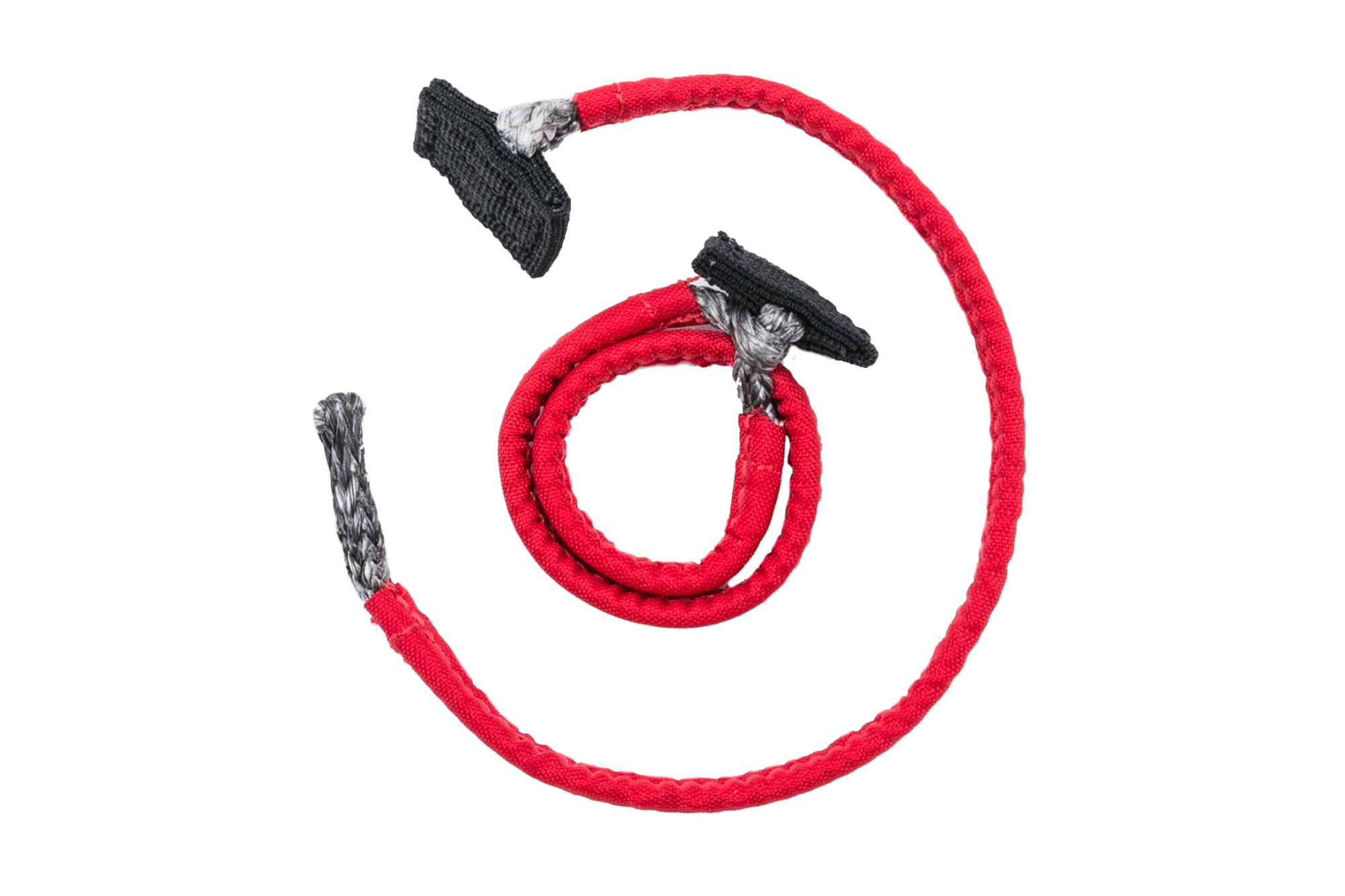
Flexible connectors
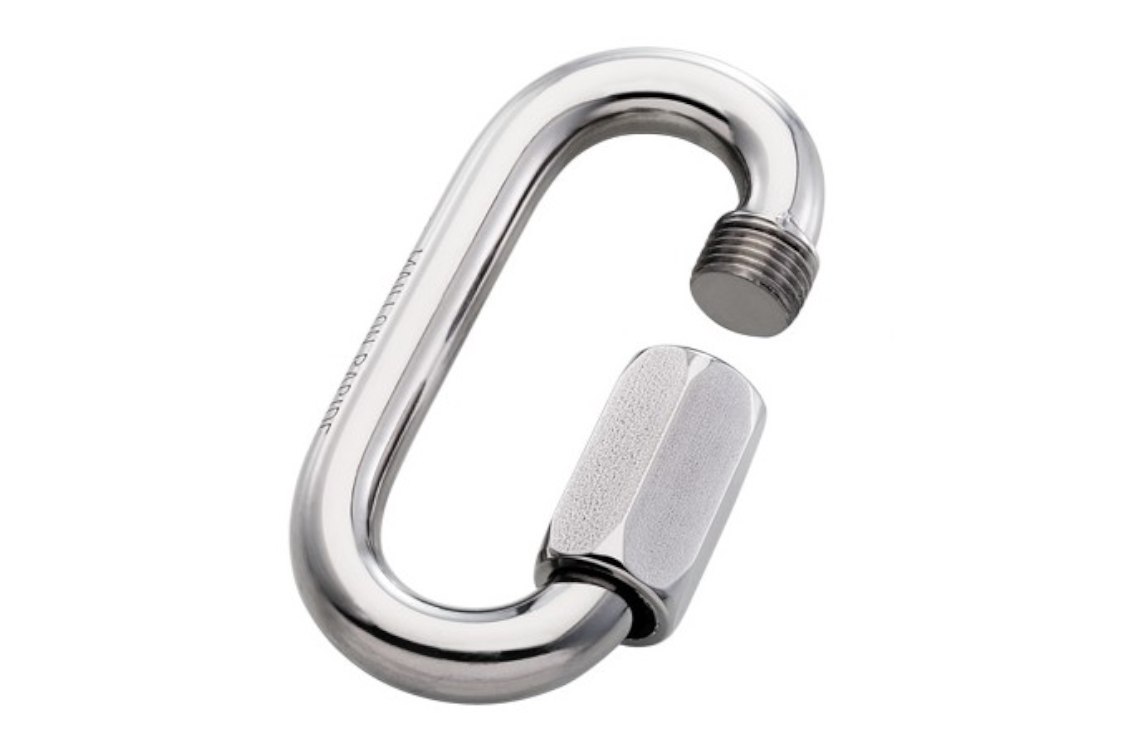
Screw links (Péguet)
The maximum strength of carabiners is therefore achieved when the workload is applied to the main axis. But the carabiner finger must also be correctly closed. Otherwise, resistance is greatly reduced, as shown by the 3rd engraved value.
To avoid this kind of inconvenience, carabiners are called "automatic" because they feature a locking system that engages automatically when the opening finger is released, without any action on the part of the user.
On the other hand, to avoid any accidental opening that would reduce resistance, the user must perform one or more specific actions to release the finger. This may involve a quarter-turn of the finger before pushing (2-step), or a small displacement of the ring before applying the quarter-turn (3-step). These systems may sometimes seem a little "complicated", requiring both hands to successfully open the carabiner, but they considerably reduce the risk of ending up in flight with an open finger carabiner that has lost more than half its strength.

"2-step opening

"3-step opening
This locking system can also be manual, with a ferrule, for example, which the user has to screw on to lock the carabiner. If the user does not screw in the ferrule, the carabiner is not fully locked, and the finger could open unexpectedly.

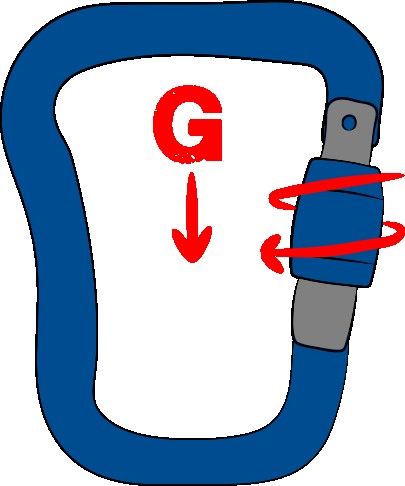
It can also be opened manually, by unscrewing the ferrule and opening the finger. This type of locking is not totally safe, as the vibrations it may be subjected to (in flight, in the trunk of the car, etc.) can eventually unscrew the ferrule and allow the finger to open. If you're using this type of carabiner (in a mountain flight, for example), we recommend placing the carabiner so that the ferrule locks downwards. In the event of vibration, gravity will help to keep the ferrule in its locked position. In the opposite direction, gravity can facilitate unscrewing together with vibrations.
Other systems may exist, but these are the main ones we'll find on the carabiners available in the paragliding world.
SPECIFICITIES OF THE RESCUE PARACHUTE
As we've just seen, a connector is designed to link 2 elements (straps or other loops). Normally, the load applied will be along the axis formed by the 2 connected elements.
The connectors seen above are therefore perfectly suitable (subject to sufficient nominal resistance) for connecting the reserve risers to the harness, or the parachute to the risers.
Most of the time, the entire reserve deployment chain is hidden from view (with the exception of the handle!) to protect the various components from external aggression (friction, Uvs, etc.) or mishandling, and to guarantee stable, reliable operation over time. It's not easy to automatically check that everything is in order.
We therefore recommend the use of :
- adapted in terms of shape to respect the working axis of the straps
- if necessary, locked with O-rings
- whose closing and locking systems are not sensitive to vibrations or other phenomena that could loosen them over time
- are not too sensitive to the direction of the applied load (multidirectional resistance)
It's also possible to connect the straps directly to each other using a "lark's head" knot, thus doing away with the need for a connector and the constraints it can entail. Despite the poor image this knot may still have, it's very efficient when executed correctly (like all knots!). Care must be taken to ensure that the connected straps are held as flat as possible, and that the knot cannot loosen or allow relative movement between the straps. Indeed, there is a high risk of breakage if tensioning is carried out after a long slide, which will induce friction and thus heating.

If there is no significant movement, there is no risk of overheating ... In fact, all the line connections on your glider are made in this way, as are all the connections between the high, medium and low lines, etc ... So it's good that it works and that it's reliable!
If the harness has no shoulder straps, or if the shoulder straps are not equipped with rescue anchor points, the only solution is to connect the rescue risers to the harness's main anchor points, where the connectors linking the glider's risers are already located. There are two options for making this connection:
- Add the emergency riser to the same connector that already connects the main wing.
This is a possible solution if there is enough space left in the connector. When the rescue is pulled, the load is normally transferred from the wing's riser to the reserve's riser as soon as the latter begins to take over. The canopy should then be neutralized and no longer have any influence on the connector.
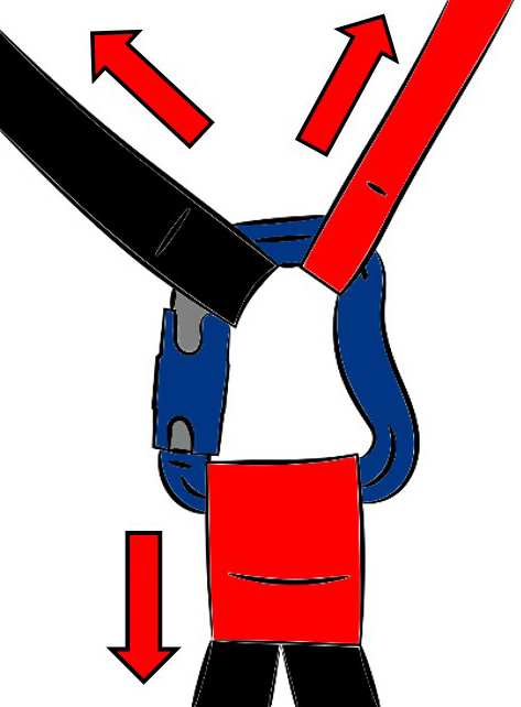
However, depending on the connector and the straps (shape, dimensions), the emergency elevator may be positioned at an angle, altering the working axis: in the event of a mirror effect, for example, or if it gets caught in the locking collar.
In this case, it's preferable to use connectors with multi-axis strength (Péguet or flexible connectors), or to bring along a line-cutting system to be able to cut one of the sail's risers should it start flying again after the rescue has been deployed. With a mirror-effect hemispherical rescue, the angle between the risers is around 90°. With a Rogallo (which has its own speed), it's possible to reach 180° and thus induce these forces in the connector's short axis, which is the weakest.

- Add another connector to separate the main and reserve sail attachments.
If the 2 risers are connected to the same anchor point with 2 separate connectors, it is also possible that a mirror effect may generate opposite forces on the anchor point. In this situation, it is the construction of the anchor point itself that will determine the strength of the assembly.
As mentionned earlier, it's a good idea to carry a line cutter with you, to be able to cut a riser in the event the wing starts re-flying and increasing the forces generated.
